Sensors
This page describes the predefined sensors and their parameters.
Sensor definition and common parameters
A sensor is attached to a vehicle by adding an XML block with the
tag name <sensor>.... </sensor> inside:
the
<vehicle>...</vehicle>that instantiates a particular robot, orthe
<vehicle:class>to have all vehicles of that type with the same sensors installed.
All sensors, via the common base C++ class mvsim::SensorBase, have the
common parameters below, with their meaning explained in the XML comments.
<!--
 ``class``: One of the registered sensor classes.
 ``name``: A name for the sensor, must be unique for each robot. If not provided,
           an automatic name will be generated. The name is important since it is
           used when publishing the sensor ROS or ZMQ topics.
-->
<sensor class="camera" name="camera1">
        <!-- Period (in seconds) between each sensor observation.
             Mathematical expressions can be used with $f{} to specify rates in Hz.
         -->
        <sensor_period>0.1</sensor_period>
        <!-- <sensor_period>$f{1/20.0}</sensor_period> -->

        <!-- See notes below -->
        <visual>
                ...
        </visual>

        <!-- Publish sensor on MVSIM ZMQ topic? (Note, **not** related to ROS at all) -->
        <!-- <publish>
                <publish_topic>/${PARENT_NAME}/${NAME}</publish_topic>
        </publish> -->
</sensor>
The <visual> tag is explained in the World XML definition of VisualObject, and
the <publish> tag in World XML definition of Simulable entities, since those tags are common
to sensors and many other entities.
Also, note that you can use the XML-level variables ${PARENT_NAME} and
${NAME} anywhere inside the sensor definition tag to refer to the parent vehicle and own sensor names,
respectively.
Each sensor class has its own additional parameters, listed in the next sections.
3D LiDARs
HELIOS 32 (26 deg FOV)
To use in your robot, copy and paste this inside a <vehicle> or <vehicle:class> tag.
<include file="$(ros2 pkg prefix mvsim)/share/mvsim/definitions/helios-32-FOV-26.sensor.xml"
  sensor_x="0.10" sensor_z="0.30"
  sensor_std_noise="0.005"
  sensor_name="lidar1"
  sensor_rate="10.0"
/>
All parameters available in helios-32-FOV-26.sensor.xml
File: mvsim_tutorial/definitions/helios-32-FOV-26.sensor.xml
<sensor class="lidar3d" name="${sensor_name|lidar1}">
    <pose_3d> ${sensor_x|0.5}  ${sensor_y|0.0}  ${sensor_z|0.7}  ${sensor_yaw|0.0} ${sensor_pitch|0.0} ${sensor_roll|0.0}</pose_3d>

    <!-- vert_fov_degrees: If defined, a symmetric vertical FOV is used.
         The alternative is using a custom list of angles in "vertical_ray_angles"
    -->
    <!-- <vert_fov_degrees>${vert_fov_degrees|70}</vert_fov_degrees> -->

    <vert_nrays>32</vert_nrays>
    <vertical_ray_angles>-16 -14.5 -13 -12.5 -11 -9.5 -8 -7 -6.5 -6.0 -5.5 -5.0 -4.5 -4.0 -3.5 -3.0 -2.5 -2.0 -1.5 -1.0 -0.5 0 0.5 1.0 1.5 2.0 2.5 3.0 3.5 6.0 8.0 10.0</vertical_ray_angles>

    <!-- Horizontal / azimuth angular resolution:
        The rotation of the Helios sensor configurable: 5 / 10 / 20 Hz
        Firing timing of the sensor is fixed at 55.296 μs (=18.084 kHz).

        Set the "sensor_rate" (Hz) variable from the parent XML to automatically
        adjust the number of points per horizontal line.
    -->
    <sensor_period>$f{1.0/${sensor_rate|10}}</sensor_period>
    <horz_nrays>$f{(1.0/${sensor_rate|10})/55.296e-6}</horz_nrays>

    <!-- 1.0=minimum (faster), larger values=potentially finer details captured -->
    <horz_resolution_factor>${horz_resolution_factor|1.0}</horz_resolution_factor>
    <vert_resolution_factor>${vert_resolution_factor|1.0}</vert_resolution_factor>

    <!-- Depth ratio (0 to 1) between adjacent depth image to allow linear interpolation of ranges -->
    <max_vert_relative_depth_to_interpolate>${max_vert_relative_depth_to_interpolate|0.3}</max_vert_relative_depth_to_interpolate>
    <max_horz_relative_depth_to_interpolate>${max_horz_relative_depth_to_interpolate|0.1}</max_horz_relative_depth_to_interpolate>

    <range_std_noise>${sensor_std_noise|0.005}</range_std_noise>
    <min_range>${min_range|0.20}</min_range>
    <max_range>${max_range|110.0}</max_range>

    <visual> <model_uri>${MVSIM_CURRENT_FILE_DIRECTORY}/../models/velodyne-vlp16.dae</model_uri> <model_roll>90</model_roll> </visual>

    <generate_intensity>${generate_intensity|false}</generate_intensity>

    <!-- Publish sensor on MVSIM ZMQ topic? (Note, this is **not** related to ROS at all) -->
    <publish enabled="${sensor_publish|false}">
        <publish_topic>/${PARENT_NAME}/${NAME}</publish_topic>
    </publish>
</sensor>
HELIOS 32 (31 deg FOV)
To use in your robot, copy and paste this inside a <vehicle> or <vehicle:class> tag.
<include file="$(ros2 pkg prefix mvsim)/share/mvsim/definitions/helios-32-FOV-31.sensor.xml"
  sensor_x="0.10" sensor_z="0.30"
  sensor_std_noise="0.005"
  sensor_name="lidar1"
  sensor_rate="10.0"
/>
All parameters available in helios-32-FOV-31.sensor.xml
File: mvsim_tutorial/definitions/helios-32-FOV-31.sensor.xml
<sensor class="lidar3d" name="${sensor_name|lidar1}">
    <pose_3d> ${sensor_x|0.5}  ${sensor_y|0.0}  ${sensor_z|0.7}  ${sensor_yaw|0.0} ${sensor_pitch|0.0} ${sensor_roll|0.0}</pose_3d>

    <!-- vert_fov_degrees: If defined, a symmetric vertical FOV is used.
         The alternative is using a custom list of angles in "vertical_ray_angles"
    -->
    <!-- <vert_fov_degrees>${vert_fov_degrees|70}</vert_fov_degrees> -->

    <vert_nrays>32</vert_nrays>
    <vertical_ray_angles>15 14 13 12 11 10 9 8 7 6 5 4 3 2 1 0 -1 -2 -3 -4 -5 -6 -7 -8 -9 -10 -11 -12 -13 -14 -15 -16</vertical_ray_angles>

    <!-- Horizontal / azimuth angular resolution:
        The rotation of the Helios sensor configurable: 5 / 10 / 20 Hz
        Firing timing of the sensor is fixed at 55.296 μs (=18.084 kHz).

        Set the "sensor_rate" (Hz) variable from the parent XML to automatically
        adjust the number of points per horizontal line.
    -->
    <sensor_period>$f{1.0/${sensor_rate|10}}</sensor_period>
    <horz_nrays>$f{(1.0/${sensor_rate|10})/55.296e-6}</horz_nrays>

    <!-- 1.0=minimum (faster), larger values=potentially finer details captured -->
    <horz_resolution_factor>${horz_resolution_factor|1.0}</horz_resolution_factor>
    <vert_resolution_factor>${vert_resolution_factor|1.0}</vert_resolution_factor>

    <!-- Depth ratio (0 to 1) between adjacent depth image to allow linear interpolation of ranges -->
    <max_vert_relative_depth_to_interpolate>${max_vert_relative_depth_to_interpolate|0.3}</max_vert_relative_depth_to_interpolate>
    <max_horz_relative_depth_to_interpolate>${max_horz_relative_depth_to_interpolate|0.1}</max_horz_relative_depth_to_interpolate>

    <range_std_noise>${sensor_std_noise|0.005}</range_std_noise>
    <min_range>${min_range|0.20}</min_range>
    <max_range>${max_range|110.0}</max_range>

    <visual> <model_uri>${MVSIM_CURRENT_FILE_DIRECTORY}/../models/velodyne-vlp16.dae</model_uri> <model_roll>90</model_roll> </visual>

    <generate_intensity>${generate_intensity|false}</generate_intensity>

    <!-- Publish sensor on MVSIM ZMQ topic? (Note, this is **not** related to ROS at all) -->
    <publish enabled="${sensor_publish|false}">
        <publish_topic>/${PARENT_NAME}/${NAME}</publish_topic>
    </publish>
</sensor>
HELIOS 32 (70 deg FOV)
To use in your robot, copy and paste this inside a <vehicle> or <vehicle:class> tag.
<include file="$(ros2 pkg prefix mvsim)/share/mvsim/definitions/helios-32-FOV-70.sensor.xml"
  sensor_x="0.10" sensor_z="0.30"
  sensor_std_noise="0.005"
  sensor_name="lidar1"
  sensor_rate="10.0"
/>
All parameters available in helios-32-FOV-70.sensor.xml
File: mvsim_tutorial/definitions/helios-32-FOV-70.sensor.xml
<sensor class="lidar3d" name="${sensor_name|lidar1}">
    <pose_3d> ${sensor_x|0.5}  ${sensor_y|0.0}  ${sensor_z|0.7}  ${sensor_yaw|0.0} ${sensor_pitch|0.0} ${sensor_roll|0.0}</pose_3d>

    <!-- vert_fov_degrees: If defined, a symmetric vertical FOV is used.
         The alternative is using a custom list of angles in "vertical_ray_angles"
    -->
    <!-- <vert_fov_degrees>${vert_fov_degrees|70}</vert_fov_degrees> -->

    <vert_nrays>32</vert_nrays>
    <vertical_ray_angles>-55.020 -52.081 -49.142 -46.204 -43.265 -40.326 -37.387 -34.449 -31.510 -28.571 -25.632 -22.694 -19.755 -16.816 -13.877 -10.939 -8.000 -6.667 -5.333 -4.000 -2.667 -1.333  0.000 1.333 2.667 4.000 5.333 6.667 8.754 10.841 12.929 15</vertical_ray_angles>

    <!-- Horizontal / azimuth angular resolution:
        The rotation of the Helios sensor configurable: 5 / 10 / 20 Hz
        Firing timing of the sensor is fixed at 55.296 μs (=18.084 kHz).

        Set the "sensor_rate" (Hz) variable from the parent XML to automatically
        adjust the number of points per horizontal line.
    -->
    <sensor_period>$f{1.0/${sensor_rate|10}}</sensor_period>
    <horz_nrays>$f{(1.0/${sensor_rate|10})/55.296e-6}</horz_nrays>

    <!-- 1.0=minimum (faster), larger values=potentially finer details captured -->
    <horz_resolution_factor>${horz_resolution_factor|1.0}</horz_resolution_factor>
    <vert_resolution_factor>${vert_resolution_factor|1.0}</vert_resolution_factor>

    <!-- Depth ratio (0 to 1) between adjacent depth image to allow linear interpolation of ranges -->
    <max_vert_relative_depth_to_interpolate>${max_vert_relative_depth_to_interpolate|0.3}</max_vert_relative_depth_to_interpolate>
    <max_horz_relative_depth_to_interpolate>${max_horz_relative_depth_to_interpolate|0.1}</max_horz_relative_depth_to_interpolate>

    <range_std_noise>${sensor_std_noise|0.005}</range_std_noise>
    <min_range>${min_range|0.20}</min_range>
    <max_range>${max_range|110.0}</max_range>

    <visual> <model_uri>${MVSIM_CURRENT_FILE_DIRECTORY}/../models/velodyne-vlp16.dae</model_uri> <model_roll>90</model_roll> </visual>

    <generate_intensity>${generate_intensity|false}</generate_intensity>

    <!-- Publish sensor on MVSIM ZMQ topic? (Note, this is **not** related to ROS at all) -->
    <publish enabled="${sensor_publish|false}">
        <publish_topic>/${PARENT_NAME}/${NAME}</publish_topic>
    </publish>
</sensor>
OUSTER OS1
To use in your robot, copy and paste this inside a <vehicle> or <vehicle:class> tag.
<include file="$(ros2 pkg prefix mvsim)/share/mvsim/definitions/ouster-os1.sensor"
  sensor_x="0.10" sensor_z="0.30"
  sensor_std_noise="0.005"
  sensor_name="lidar1"
  sensor_period_sec="0.10"
/>
All parameters available in ouster-os1.sensor.xml
File: mvsim_tutorial/definitions/ouster-os1.sensor.xml
<sensor class="lidar3d" name="${sensor_name|lidar1}">
    <pose_3d> ${sensor_x|0.5}  ${sensor_y|0.0}  ${sensor_z|0.7}  ${sensor_yaw|0.0} ${sensor_pitch|0.0} ${sensor_roll|0.0}</pose_3d>

    <vert_nrays>${vert_nrays|128}</vert_nrays>

    <!-- Vertical FOV:
         - OS0: 90deg
         - OS1: 45deg
         - OS2: 22.5deg
    -->
    <vert_fov_degrees>${vert_fov_degrees|22.5}</vert_fov_degrees>

    <!-- Horizontal / azimuth angular resolution:

        Modes (number of "columns per lidar frame" x frame rate):
        - 512 x {10,20} Hz
        - 1024 x {10,20} Hz
        - 2048 x 10 Hz
    -->
    <sensor_period>${sensor_period_sec|0.10}</sensor_period>
    <horz_nrays>${sensor_horz_nrays|1024}</horz_nrays>

    <!-- 1.0=minimum (faster), larger values=potentially finer details captured -->
    <horz_resolution_factor>${horz_resolution_factor|1.0}</horz_resolution_factor>
    <vert_resolution_factor>${vert_resolution_factor|1.0}</vert_resolution_factor>

    <!-- Depth ratio (0 to 1) between adjacent depth image to allow linear interpolation of ranges -->
    <max_vert_relative_depth_to_interpolate>${max_vert_relative_depth_to_interpolate|0.3}</max_vert_relative_depth_to_interpolate>
    <max_horz_relative_depth_to_interpolate>${max_horz_relative_depth_to_interpolate|0.1}</max_horz_relative_depth_to_interpolate>

    <range_std_noise>${sensor_std_noise|0.005}</range_std_noise>
    <min_range>${min_range|0.5}</min_range>
    <max_range>${max_range|90.0}</max_range>

    <visual> <model_uri>${MVSIM_CURRENT_FILE_DIRECTORY}/../models/velodyne-vlp16.dae</model_uri> <model_roll>90</model_roll> </visual>

    <generate_intensity>${generate_intensity|false}</generate_intensity>

    <!-- Publish sensor on MVSIM ZMQ topic? (Note, this is **not** related to ROS at all) -->
    <publish enabled="${sensor_publish|false}">
        <publish_topic>/${PARENT_NAME}/${NAME}</publish_topic>
    </publish>
</sensor>
Velodyne VLP-16
To use in your robot, copy and paste this inside a <vehicle> or <vehicle:class> tag.
<include file="$(ros2 pkg prefix mvsim)/share/mvsim/definitions/velodyne-vlp16.sensor"
  sensor_x="0.10" sensor_z="0.30"
  sensor_std_noise="0.005"
  sensor_name="lidar1"
  sensor_rpm="600"
/>
All parameters available in velodyne-vlp16.sensor.xml
File: mvsim_tutorial/definitions/velodyne-vlp16.sensor.xml
<sensor class="lidar3d" name="${sensor_name|lidar1}">
    <pose_3d> ${sensor_x|0.5}  ${sensor_y|0.0}  ${sensor_z|0.7}  ${sensor_yaw|0.0} ${sensor_pitch|0.0} ${sensor_roll|0.0}</pose_3d>

    <vert_fov_degrees>${vert_fov_degrees|30}</vert_fov_degrees>
    <vert_nrays>${vert_nrays|16}</vert_nrays>

    <!-- Horizontal / azimuth angular resolution:
        The rotation of the Velodyne VLP16 ("PUCK") sensor is configurable
        between 300 RPM and 1200 RPM => 5-20 Hz.
        Firing timing of the sensor is fixed at 55.296 μs (=18.084 kHz).

        Set the "sensor_rpm" variable from the parent XML to automatically
        adjust the number of points per horizontal line, and the sensor
        rate (Hz).
    -->
    <sensor_period>$f{60.0/${sensor_rpm|600}}</sensor_period>
    <horz_nrays>$f{(60.0/${sensor_rpm|600})/55.296e-6}</horz_nrays>

    <!-- 1.0=minimum (faster), larger values=potentially finer details captured -->
    <horz_resolution_factor>${horz_resolution_factor|1.0}</horz_resolution_factor>
    <vert_resolution_factor>${vert_resolution_factor|1.0}</vert_resolution_factor>

    <!-- Depth ratio (0 to 1) between adjacent depth image to allow linear interpolation of ranges -->
    <max_vert_relative_depth_to_interpolate>${max_vert_relative_depth_to_interpolate|0.3}</max_vert_relative_depth_to_interpolate>
    <max_horz_relative_depth_to_interpolate>${max_horz_relative_depth_to_interpolate|0.1}</max_horz_relative_depth_to_interpolate>

    <range_std_noise>${sensor_std_noise|0.005}</range_std_noise>
    <max_range>${max_range|80.0}</max_range>

    <visual> <model_uri>${MVSIM_CURRENT_FILE_DIRECTORY}/../models/velodyne-vlp16.dae</model_uri> <model_roll>90</model_roll> </visual>

    <generate_intensity>${generate_intensity|false}</generate_intensity>

    <!-- Publish sensor on MVSIM ZMQ topic? (Note, this is **not** related to ROS at all) -->
    <publish enabled="${sensor_publish|false}">
        <publish_topic>/${PARENT_NAME}/${NAME}</publish_topic>
    </publish>
</sensor>
RGB camera
A regular RGB (color) pin-hole camera (without lens distortion at present). The user must provide the camera intrinsic and extrinsic parameters:
To use in your robot, copy and paste this inside a <vehicle> or <vehicle:class> tag.
<include file="$(ros2 pkg prefix mvsim)/share/mvsim/definitions/camera.sensor.xml"
        sensor_x="0.1" sensor_y="0.0" sensor_z="0.8"
        ncols="800"    nrows="600"
        cx="$f{800/2}" cy="$f{600/2}"
        fx="800" fy="800"
        sensor_period_sec="$f{1/20.0}"
        clip_min="0.02" clip_max="300"
        sensor_visual_scale="0.2"
/>
All parameters available in camera.sensor.xml
File: mvsim_tutorial/definitions/camera.sensor.xml
<sensor class="camera" name="${sensor_name|camera1}">
    <!--
        * pose_3d: Pose of the RGB camera sensor on the robot (+Z forward)
        See: https://docs.mrpt.org/reference/latest/class_mrpt_obs_CObservationImage.html
    -->
    <pose_3d> ${sensor_x|0.65}  ${sensor_y|0.0}  ${sensor_z|1.0}  ${sensor_yaw|-90.0} ${sensor_pitch|0} ${sensor_roll|-90.0}</pose_3d>

    <sensor_period>${sensor_period_sec|0.1}</sensor_period>

    <ncols>${ncols|640}</ncols>
    <nrows>${nrows|480}</nrows>
    <cx>${cx|320}</cx>
    <cy>${cy|240}</cy>
    <fx>${fx|400}</fx>
    <fy>${fy|400}</fy>
    <clip_min>${clip_min|1e-2}</clip_min>
    <clip_max>${clip_max|1e+4}</clip_max>

    <visual>
      <model_uri>${MVSIM_CURRENT_FILE_DIRECTORY}/../models/simple_camera.dae</model_uri>
      <model_scale>${sensor_visual_scale|1.0}</model_scale>
    </visual>

    <!-- Publish sensor on MVSIM ZMQ topic? (Note, this is **not** related to ROS at all) -->
    <publish enabled="${sensor_publish|false}">
        <publish_topic>/${PARENT_NAME}/${NAME}</publish_topic>
    </publish>

</sensor>
IMU
An inertial sensor that measures (in the current version of MVSim):
3D linear proper acceleration.
3D angular velocity.
(Optionally) 3D orientation as a quaternion.
To use in your robot, copy and paste this inside a <vehicle> or <vehicle:class> tag.
<include file="$(ros2 pkg prefix mvsim)/share/mvsim/definitions/imu.sensor.xml"
        sensor_x="0.0" sensor_y="0.0" sensor_z="0.0"
        sensor_period_sec="$f{1/200.0}"
/>
All parameters available in imu.sensor.xml
File: mvsim_tutorial/definitions/imu.sensor.xml
<sensor class="imu" name="${sensor_name|imu1}">
    <pose_3d> ${sensor_x|0}  ${sensor_y|0.0}  ${sensor_z|0}  ${sensor_yaw|0.0} ${sensor_pitch|0.0} ${sensor_roll|0.0}</pose_3d>
    <sensor_period>${sensor_period_sec|0.05}</sensor_period>

    <!-- White-noise standard deviations (measurement noise / angle random walk).
         These correspond to the legacy params angular_velocity_std_noise and
         linear_acceleration_std_noise and remain backward-compatible. -->
    <angular_velocity_white_noise_std_noise>${sensor_angular_velocity_white_noise_std_noise|2e-4}</angular_velocity_white_noise_std_noise>
    <linear_acceleration_white_noise_std_noise>${sensor_linear_acceleration_white_noise_std_noise|0.017}</linear_acceleration_white_noise_std_noise>

    <!-- Bias random-walk standard deviations (in-run stability / drift).
         Units: rad/s/sqrt(s) for gyroscope, m/s²/sqrt(s) for accelerometer.
         Set to 0 to disable bias drift (default).
         See: Forster et al., "On-Manifold Preintegration for Real-Time
         Visual-Inertial Odometry", IEEE T-RO 2016. -->
    <angular_velocity_random_walk_std_noise>${sensor_angular_velocity_random_walk_std_noise|0}</angular_velocity_random_walk_std_noise>
    <linear_acceleration_random_walk_std_noise>${sensor_linear_acceleration_random_walk_std_noise|0}</linear_acceleration_random_walk_std_noise>

    <measure_orientation>${sensor_measure_orientation|false}</measure_orientation>

    <visual enabled="${sensor_custom_visual|true}">
        <model_uri>${MVSIM_CURRENT_FILE_DIRECTORY}/../models/simple_imu.dae</model_uri>
    </visual>

    <!-- Publish sensor on MVSIM ZMQ topic? (Note, this is **not** related to ROS at all) -->
    <publish enabled="${sensor_publish|false}">
        <publish_topic>/${PARENT_NAME}/${NAME}</publish_topic>
    </publish>
</sensor>
IMU noise model
The IMU sensor implements the standard continuous-time stochastic error model described in [Forster2016], with two independent noise components per axis for both the gyroscope and accelerometer channels:
- White noise (measurement noise).
Zero-mean Gaussian noise added to every sample. Configured via the
*_white_noise_std_noiseparameters (standard deviation in the channel units:rad/sfor gyroscope,m/s²for accelerometer).- Bias random walk (in-run stability / drift).
A slowly-varying bias modelled as a Wiener process (integral of white noise). Configured via the
*_random_walk_std_noiseparameters (units:rad/s/√sfor gyroscope,m/s²/√sfor accelerometer). Set to0(default) to disable bias drift.
The discrete-time update at each simulation step of duration \(\Delta t\) is:
The four XML parameters are:
Parameter |
Default |
Description |
|---|---|---|
|
|
Gyroscope white noise σ (rad/s) |
|
|
Accelerometer white noise σ (m/s²) |
|
|
Gyroscope bias random walk σ (rad/s/√s) |
|
|
Accelerometer bias random walk σ (m/s²/√s) |
Note
The legacy parameter names angular_velocity_std_noise and
linear_acceleration_std_noise are still accepted and map to the
corresponding *_white_noise_std_noise parameters.
Example — a noisy tactical-grade IMU with bias drift:
<include file="$(ros2 pkg prefix mvsim)/share/mvsim/definitions/imu.sensor.xml"
  sensor_x="0.0" sensor_y="0.0" sensor_z="0.0"
  sensor_period_sec="$f{1/200.0}"
  sensor_angular_velocity_white_noise_std_noise="1.7e-4"
  sensor_linear_acceleration_white_noise_std_noise="5.88e-3"
  sensor_angular_velocity_random_walk_std_noise="1.0e-5"
  sensor_linear_acceleration_random_walk_std_noise="3.0e-4"
/>
C. Forster, L. Carlone, F. Dellaert, D. Scaramuzza, “On-Manifold Preintegration for Real-Time Visual-Inertial Odometry”, IEEE Transactions on Robotics, vol. 33, no. 1, pp. 1-21, 2016.
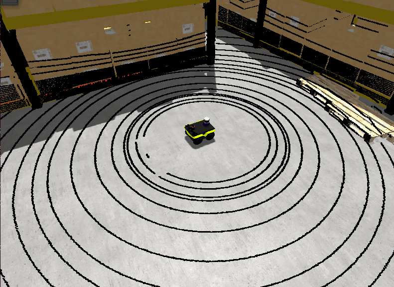
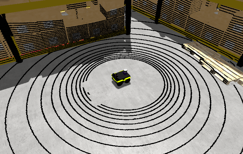
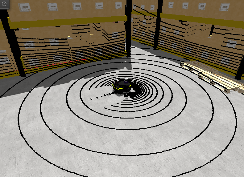
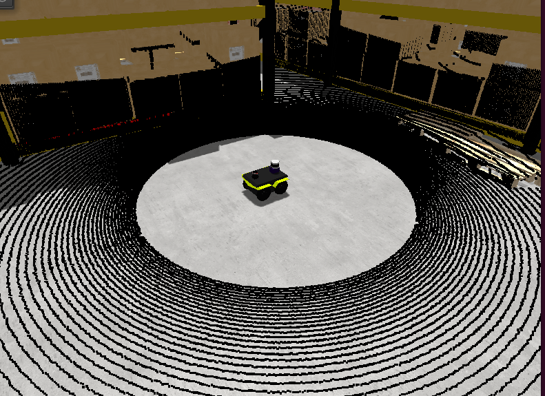
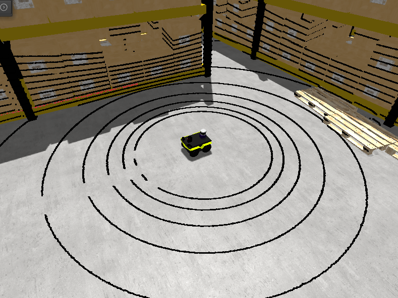
2D laser scanner
“Classical” lidars that scan obstacles in a plane only. These includes are available for these sensors:
Generic 2D LIDAR
To use in your robot, copy and paste this inside a <vehicle> or <vehicle:class> tag.
Important parameters:
raytrace_3d=false(DEFAULT), Very fast simulation using approximate 2D shapes of world elements.raytrace_3d=true: It uses GPU-based raytracing for exact distance calculation to world elements of arbitrary 3D shapes.
<include file="$(ros2 pkg prefix mvsim)/share/mvsim/definitions/lidar2d.sensor.xml"
        sensor_x="0.2" sensor_y="0" sensor_z="0.50" sensor_yaw="0"
        sensor_period_sec="0.10"
        sensor_nrays="181"
        raytrace_3d="true"
        fov_degrees="270"
        sensor_name="scanner1"
>
All parameters available in lidar2d.sensor.xml
File: mvsim_tutorial/definitions/lidar2d.sensor.xml
<sensor class="laser" name="${sensor_name|laser1}">
    <pose_3d> ${sensor_x|1.80}  ${sensor_y|0.0}  ${sensor_z|0.7}  ${sensor_yaw|0.0} 0.0 0.0</pose_3d>
    <fov_degrees>${fov_degrees|180}</fov_degrees>
    <sensor_period>${sensor_period_sec|0.05}</sensor_period>
    <nrays>${sensor_nrays|181}</nrays>
    <range_std_noise>${sensor_std_noise|0.01}</range_std_noise>
    <angle_std_noise_deg>${sensor_std_noise_deg|0.01}</angle_std_noise_deg>
    <raytrace_3d>${raytrace_3d|false}</raytrace_3d>
    <max_range>${max_range|30.0}</max_range>

    <visual enabled="${sensor_custom_visual|true}">
        <model_uri>${MVSIM_CURRENT_FILE_DIRECTORY}/../models/hokuyo_utm30.dae</model_uri>
    </visual>

    <!-- Publish sensor on MVSIM ZMQ topic? (Note, this is **not** related to ROS at all) -->
    <publish enabled="${sensor_publish|false}">
        <publish_topic>/${PARENT_NAME}/${NAME}</publish_topic>
    </publish>

    <!-- Visualization of sensed points in MVSIM GUI -->
    <viz_visiblePoints>${viz_visiblePoints|true}</viz_visiblePoints>
    <viz_pointSize>${viz_pointSize|3.0}</viz_pointSize>
    <viz_visiblePlane>${viz_visiblePlane|false}</viz_visiblePlane>
    <viz_visibleLines>${viz_visibleLines|true}</viz_visibleLines>
    <viz_pointsColor>${viz_pointsColor|#ff000080}</viz_pointsColor>
    <viz_planeColor>${viz_planeColor|#0000ff10}</viz_planeColor>

</sensor>
RPLidar A2
Just like the generic Lidar above, but with a custom visualization for this particular commercial model.
To use in your robot, copy and paste this inside a <vehicle> or <vehicle:class> tag.
Important parameter: See notes on raytrace_3d above.
<include file="$(ros2 pkg prefix mvsim)/share/mvsim/definitions/rplidar-a2.sensor.xml"
        sensor_x="0.2" sensor_y="0" sensor_z="0.50" sensor_yaw="0"
        sensor_period_sec="0.10"
        sensor_nrays="181"
        raytrace_3d="true"
        fov_degrees="270"
        sensor_name="scanner1"
>
All parameters available in rplidar-a2.sensor.xml
File: mvsim_tutorial/definitions/rplidar-a2.sensor.xml
<sensor class="laser" name="${sensor_name|laser1}">
    <pose_3d> ${sensor_x|1.80}  ${sensor_y|0.0}  ${sensor_z|0.7}  ${sensor_yaw|0.0} ${sensor_pitch|0.0} ${sensor_roll|0.0}</pose_3d>
    <fov_degrees>${fov_degrees|360}</fov_degrees>

    <!-- Horizontal / azimuth angular resolution:
        The rotation of the RPLIDAR sensor is configurable
        between 5-15 Hz.
        Firing timing of the sensor is fixed at 125 μs (=8 kHz).

        Set the "sensor_rpm" variable from the parent XML to automatically
        adjust the number of points and the sensor scan rate (Hz).
    -->
    <sensor_period>$f{1/${sensor_hz|10}}</sensor_period>
    <nrays>$f{(1/${sensor_hz|10})/125e-6}</nrays>

    <range_std_noise>${sensor_std_noise|0.01}</range_std_noise>
    <angle_std_noise_deg>${sensor_std_noise_deg|0.01}</angle_std_noise_deg>

    <raytrace_3d>${raytrace_3d|false}</raytrace_3d>
    <max_range>${max_range|16.0}</max_range>

    <visual>
        <model_uri>https://mrpt.github.io/mvsim-models/turtlebot3.zip/turtlebot3/lds.dae</model_uri>
        <model_roll>90</model_roll>
        <model_scale>0.001</model_scale>
    </visual>

    <!-- Publish sensor on MVSIM ZMQ topic? (Note, this is **not** related to ROS at all) -->
    <publish enabled="${sensor_publish|false}">
        <publish_topic>/${PARENT_NAME}/${NAME}</publish_topic>
    </publish>

    <!-- Visualization of sensed points in MVSIM GUI -->
    <viz_visiblePoints>${viz_visiblePoints|true}</viz_visiblePoints>
    <viz_pointSize>${viz_pointSize|3.0}</viz_pointSize>
    <viz_visiblePlane>${viz_visiblePlane|false}</viz_visiblePlane>
    <viz_visibleLines>${viz_visibleLines|true}</viz_visibleLines>
    <viz_pointsColor>${viz_pointsColor|#ff000080}</viz_pointsColor>
    <viz_planeColor>${viz_planeColor|#0000ff10}</viz_planeColor>

</sensor>
Depth (RGBD) camera
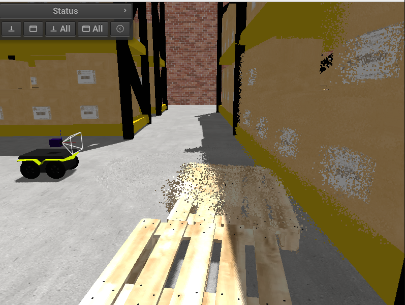
An RGB+D (color plus depth) camera sensor, similar to an Intel RealSense or ASUS Xtion / Astra. It simulates both the RGB and depth channels independently (each with its own intrinsics and clip distances) and can optionally publish to ROS the following topics:
Topic |
Type |
Notes |
|---|---|---|
|
|
RGB image (always published when |
|
|
XYZ pointcloud, or XYZRGB if |
|
|
16UC1 depth image (each pixel = depth in |
|
|
Depth camera intrinsics. Published when |
To use in your robot, copy and paste this inside a <vehicle> or <vehicle:class> tag.
<include file="$(ros2 pkg prefix mvsim)/share/mvsim/definitions/rgbd_camera.sensor.xml"
  sensor_x="0.2" sensor_y="0"  sensor_z="0.29"
  sensor_period_sec="0.10"
  show_3d_pointcloud="true"
  publish_ros_depth_image="true"
  publish_ros_colored_pointcloud="false"
/>
All parameters available in rgbd_camera.sensor.xml
File: mvsim_tutorial/definitions/rgbd_camera.sensor.xml
<sensor class="rgbd_camera" name="${sensor_name|camera1}">
    <!--
        * pose_3d: Pose of the depth sensor on the robot (+X forward)
        * relativePoseIntensityWRTDepth: RGB camera wrt depth sensor (+Z forward, and possibly an offset)
        See: https://docs.mrpt.org/reference/latest/class_mrpt_obs_CObservation3DRangeScan.html
    -->
    <pose_3d> ${sensor_x|0.65}  ${sensor_y|0.0}  ${sensor_z|1.0}  ${sensor_yaw|0.0} ${sensor_pitch|0.0} ${sensor_roll|0.0}</pose_3d>

    <!-- the yaw=-90deg roll=-90deg rotation is required since RGB axis convention is +Z forward, depth sensor is +X forward -->
    <relativePoseIntensityWRTDepth>0.0 0.0 0.0  -90.0 0.0 -90.0</relativePoseIntensityWRTDepth>

    <sensor_period>${sensor_period_sec|0.1}</sensor_period>

    <sense_depth>${sense_depth|true}</sense_depth>
    <sense_rgb>${sense_rgb|true}</sense_rgb>

    <show_3d_pointcloud>${show_3d_pointcloud|false}</show_3d_pointcloud>

    <!-- ROS publishing options for depth image & colored pointcloud -->
    <publish_ros_depth_image>${publish_ros_depth_image|true}</publish_ros_depth_image>
    <publish_ros_colored_pointcloud>${publish_ros_colored_pointcloud|false}</publish_ros_colored_pointcloud>

    <depth_ncols>640</depth_ncols>
    <depth_nrows>480</depth_nrows>
    <depth_cx>320</depth_cx>
    <depth_cy>240</depth_cy>
    <depth_fx>400</depth_fx>
    <depth_fy>400</depth_fy>
    <depth_resolution>1e-3</depth_resolution>
    <depth_clip_min>${depth_clip_min|0.01}</depth_clip_min>
    <depth_clip_max>${depth_clip_max|15.0}</depth_clip_max>
    <depth_noise_sigma>${depth_noise_sigma|0.05}</depth_noise_sigma>

    <rgb_ncols>640</rgb_ncols>
    <rgb_nrows>480</rgb_nrows>
    <rgb_cx>320</rgb_cx>
    <rgb_cy>240</rgb_cy>
    <rgb_fx>400</rgb_fx>
    <rgb_fy>400</rgb_fy>
    <rgb_clip_min>${rgb_clip_min|1e-2}</rgb_clip_min>
    <rgb_clip_max>${rgb_clip_max|1e+4}</rgb_clip_max>

    <visual> <model_uri>${MVSIM_CURRENT_FILE_DIRECTORY}/../models/simple_camera.dae</model_uri> <model_pitch>90</model_pitch> </visual>

    <!-- Publish sensor on MVSIM ZMQ topic? (Note, this is **not** related to ROS at all) -->
    <publish enabled="${sensor_publish|false}">
        <publish_topic>/${PARENT_NAME}/${NAME}</publish_topic>
    </publish>

</sensor>
ROS publishing options
publish_ros_depth_image(default:true)When enabled, the sensor publishes the depth channel as a separate
sensor_msgs/Imagemessage encoded as 16UC1 on the topic<label>_depth/image_raw, together with a matchingsensor_msgs/CameraInfoon<label>_depth/camera_info. This matches the topic layout of real RGBD cameras such as the ASUS Xtion / Astra (/depth/image_raw).publish_ros_colored_pointcloud(default:false)When enabled and the sensor has
sense_rgb=true, the pointcloud published on<label>_pointswill include per-point RGB color (XYZRGBfields) instead of plainXYZ.
GNSS sensor (“GPS”)
A “GPS sensor” can be attached to a robot with the code shown below.
For it to work, the world XML needs to have a georeference tag.
To use in your robot, copy and paste this inside a <vehicle> or <vehicle:class> tag.
<include file="$(ros2 pkg prefix mvsim)/share/mvsim/definitions/gnss.sensor.xml"
  sensor_x="0.0"  sensor_y="0.0" sensor_z="0.50"
  sensor_period_sec="1.0"
  sensor_name="gps"
  sensor_horizontal_std_noise="1.5"
  sensor_vertical_std_noise="2.5"
  />
All parameters available in gnss.sensor.xml
File: mvsim_tutorial/definitions/gnss.sensor.xml
<sensor class="gnss" name="${sensor_name|gps1}">
    <pose_3d> ${sensor_x|0}  ${sensor_y|0.0}  ${sensor_z|0}  ${sensor_yaw|0.0} ${sensor_pitch|0.0} ${sensor_roll|0.0}</pose_3d>
    <sensor_period>${sensor_period_sec|1.0}</sensor_period>

    <!-- Sensor 1-sigma noise [meters] -->
    <horizontal_std_noise>${sensor_horizontal_std_noise|2.0}</horizontal_std_noise>
    <vertical_std_noise>${sensor_vertical_std_noise|4.0}</vertical_std_noise>

    <visual enabled="${sensor_custom_visual|true}">
        <model_uri>${MVSIM_CURRENT_FILE_DIRECTORY}/../models/simple_imu.dae</model_uri>
    </visual>

    <!-- Publish sensor on MVSIM ZMQ topic? (Note, this is **not** related to ROS at all) -->
    <publish enabled="${sensor_publish|false}">
        <publish_topic>/${PARENT_NAME}/${NAME}</publish_topic>
    </publish>
</sensor>